|
Using
the
Garmin G1000
Glass
Cockpit
By Doug Horton *
An exciting addition to FSX is
the “glass panel cockpit” feature, which is
furnished with three aircraft in the Deluxe version:
The control panels of these aircraft feature the G1000®
system, which Garmin indicates “is a completely
integrated avionics system designed to fit a broad range
of aircraft models. It’s an all-glass flight deck that
presents flight instrumentation, location, navigation,
communication, and identification data on large-format,
high-resolution displays. The digital data presentation
on the G1000 puts all flight-critical information
literally at the pilot’s fingertips.” Here are some of
the advertised features of the real G1000 system:
-
Large-format LCD displays —
interchangeable for use as Primary Flight Display (PFD)
or Multi-Function Display (MFD).
-
Available with two- or three-axis flight control (autopilot)
system
-
Selectable PFD view features
-
Moving-map MFD with engine/fuel gauge cluster and
checklist capability
-
Built-in Comm and Nav communications transceivers
-
Mode-S transponders with Traffic Information Service (TIS)
-
Worldwide terrain and obstacle database
-
Interfaces for terrain, traffic, lightning and weather
sensors
-
Ethernet connectivity for updates
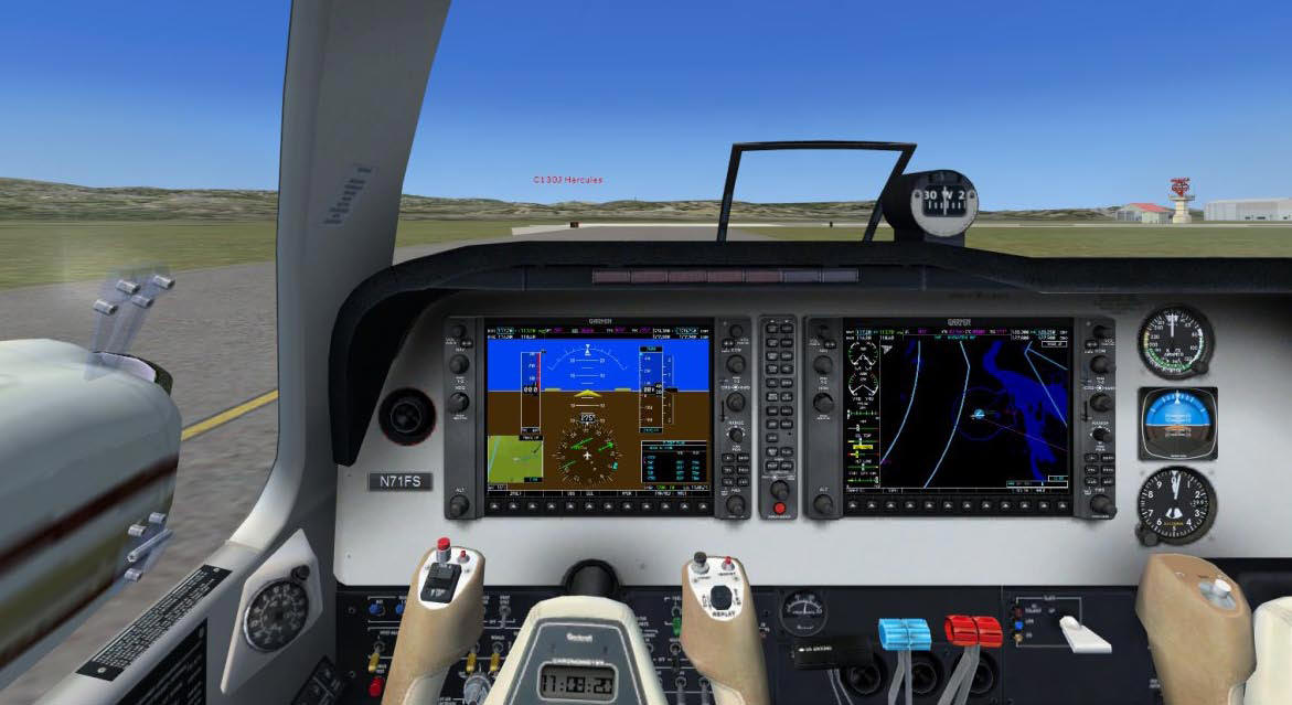
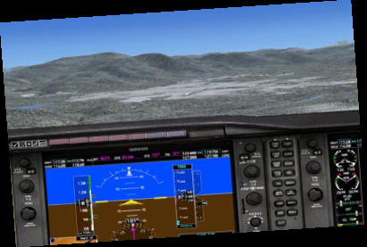
Accompanying screenshots show both 2D
and virtual cockpit control panel views. In the 2D view,
the MFD is available as a sub-panel, which is displayed
by clicking the GPS icon or by pressing Shift+3 for all
three aircraft furnished with the G1000.
|
 |
 |
|
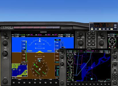
Baron 2D panel view, showing G1000 PFD on left,
with MFD and AP sub-panels open |
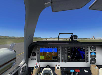
The FSX Baron virtual cockpit shows both
G1000 PFD and MFD displays. |
According to the FSX Learning Center, “the G1000 in
Flight Simulator doesn’t model all of the G1000’s
features (and new features are being added all the time).
It does however model most of what a typical private
pilot would use on a typical VFR or IFR flight (using an
early model G1000).” Read the G1000 description in the
Learning Center, or for easier reading, point your
browser to (FSX)\FSWeb\LearningCenter\Navigation\UsingTheG1000.htm.
Tutorial Flight
A tutorial flight will demonstrate many features of the
G1000. From the FSX Free Flight interface, select the
Beechcraft Baron 58 with G1000, morning departure time,
clear weather, and Concord (California) Buchanan (KCCR)
Airport, with Parking 9 - Ramp GA Small, for a short
taxi to Runway 1L or 1R.
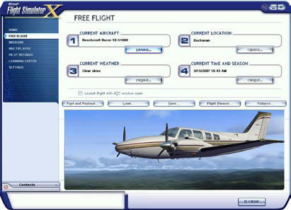 |
| Initial setup of G1000
tutorial flight |
Employ the FSX Flight Planner to
create a flight plan from KCCR to Truckee-Tahoe Airport
(KTRK). Plan the flight for VFR along low altitude
airways. After clicking Find to generate a plan, edit
the plan to delete the intersections shown, and drag the
track line to the HNW VOR to insert this waypoint into
the plan. Accept altitude 13,500, which is the Minimum
Enroute Altitude (MEA) for the airways along which we’ll
fly.
The tutorial flight will depart from the San Francisco
Bay area, pass slightly south of Sacramento, fly over
the agricultural San Joaquin Valley, climb to 13,500
feet over the scenic Sierra Nevada Mountains, then
descend and land at Truckee-Tahoe airport at elevation
5,900 feet MSL. Use the FSX ATC feature if you wish, as
KCCR is a towered airport, and after departure, contact
Travis Departure and request Flight Following.
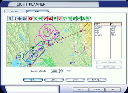 |
VFR flight plan from
Concord Buchanan (KCCR)
to Truckee-Tahoe (KTRK) |
Communications and Navigation Radios
The G1000 includes two VHF communications and navigation
radios, which are highlighted by yellow ovals in the
accompanying image – Nav on the left and Comm on the
right side of the PFD and MFD. Each radio has an active
and standby frequency controlled by the key with a
double-ended arrow. The active frequency for the Nav
radios is on the right, while the active frequency for
Comm radios is on the left – in each case, the active
frequency is that which is closer to the center of the
PFD or MFD.
The green tuning boxes are controlled by clicking at the
bottom of the respective tuning knobs, when the mouse
cursor changes to a hand. You’ll see the box move up and
down between the Nav1 and Nav2 or Comm1 and Comm2. The
whole and fractional frequencies are changed up or down
by clicking – and + signs that appear when the mouse
cursor is moved around the perimeter of the knobs. The
upper set (large knob) of – and + signs controls the
whole-number frequencies and the lower set (small knob)
controls the fractional frequencies.
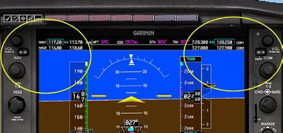 |
| Nav and Comm radio contntrols are highlighteted on the
G1000 PFD |
Transponder
The transponder communications function is also included
in the G1000. The transponder code defaults to 1200,
which is the standard code for VFR flights in the U.S.
If you’re flying IFR, you’ll need to set the “squawk”
code assigned by ATC, and in real flying, it’s not
unusual for ATC to change the assigned code during a
flight.
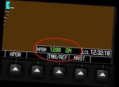 |
| The current transponder
setting and status are displayed at the lower
right of the PFD |
To set or change the transponder
code, press the XPDR softkey on the PFD, then press
either the VFR softkey to change the code to 1200, or
CODE to set an assigned number. The latter action will
change the eight leftmost softkeys to the digits 0
through 7. You then press the assigned digits in order,
though we’ll not do this now, so we retain the default
1200 code. Press the BACK softkey twice to return to the
default display.
 |
Pressing the XPDR softkey
then the CODE soft key allows
viewing and setting of the Transponder frequency |
Next to the displayed transponder
code, the indication ON appears in green. This does not
seem to change in the FSX version of the G1000, though
in the real version, the user can select ON, STANDBY,
ALT, and IDENT by softkey after pressing the XPDR
softkey. Additionally in the real version, the
indication automatically reads GND when the aircraft is
on the ground and ALT when the aircraft is airborne.
Also in the real version, a small R appears periodically
in the right-hand side of the transponder display
whenever the transponder replies to an interrogation by
ground equipment.
Autopilot
Autopilot heading and altitude settings are controlled
by respective HDG and ALT knobs on the left sides of the
G1000 PFD and MFD. Pressing the HDG knob, by clicking
under the knob, synchronizes the heading setting with
the aircraft’s present heading – moving the HSI heading
bug to the current heading. The ALT knob is a dual knob,
and careful positioning of the mouse cursor will reveal
– and + signs for the inner and outer knobs,
corresponding to hundreds and thousands, respectively.
Operating the HDG and ALT knobs is intuitive, but where
are the other autopilot controls? Surprisingly, we need
to press Shift+2 to pop up the familiar Bendix King
autopilot panel from previous FS versions, as shown in
the 2D panel screenshot on the first page. This is an
unfortunate departure of the FSX G1000 from reality, as
the real G1000 autopilot (Automatic Flight Control
System) keys are located between the HDG and ALT knobs
onthe left side of the real MFD, as shown in the
accompanying image.
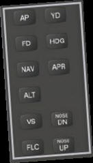 |
| Autopilot (AFCS) keys on
left side of real G1000 MFD |
Next, we must locate the NAV/GPS
switch. In the Beechcraft Baron 58, it’s located on the
electrical panel, which is displayed with Shift+7, and
in the Mooney Bravo, it’s Shift+8. A NAV/GPS switch for
the G1000 version of the FSX Cessna 172 seems to be
missing from the main panel and all subpanels – an
apparent bug.
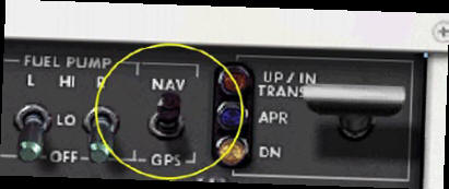 |
| Nav/GPS switch on
Beechcraft Baron 58 electrical panel |
Before takeoff VFR from KCCR, take
the following steps: 1. On the
electrical sub-panel, set the NAV/GPS switch to GPS.
2. On the G1000 PFD or MFD, use the ALT knob to set the
initial altitude to 5500 feet (odd-numbered altitude for
easterly course plus 500 for VFR). You’ll see the
altitude preset number change on the PFD above the
altitude tape.
3. On the G1000 PFD, press the CDI softkey until the HSI
indicates GPS ENR. The HSI indication and the needle
graphic will change color to pink.
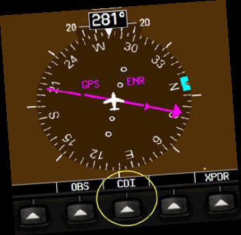 |
| The CDI softkey controls
the heading reference for the HSI |
Go ahead with takeoff, and when
airborne, press the autopilot AP, NAV, and HDG keys to
engage the autopilot and cause the G1000 to follow the
flight plan and climb the plane to 5500 feet. Press
Shift+4 on the 2D panel to monitor flight progress on
the MFD. Set its range display to 80 nm, then pause the
flight after passing the Sacramento (SAC) VOR and the
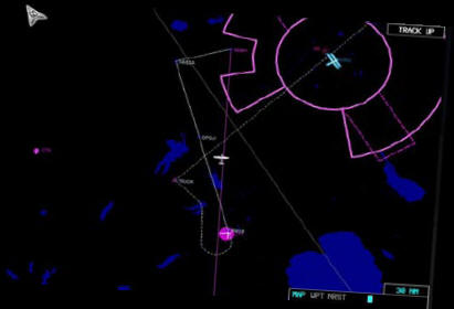
KMHR airport. After passing KMHR,
reset the autopilot altitude to 13,500 feet. Another
feature of the G1000 is the capability to display
terrain on the MFD, as shown in the accompanying image,
with user aircraft just past the KMHR airport. To change
from the black background to terrain background, press
the MAP softkey, then press again after this softkey
changes to TOPO.
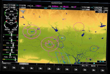 |
| Pressing the MAP, then
TOPO softkey changes MFD display background to
terrain |
“Going Direct” on a GPS flight
plan. Though FSX’s ATC feature does not provide for
skipping waypoints and going direct to a subsequent
waypoint on a flight plan, this action is very realistic
in real flying, in order to “cut corners” on the route.
Suppose for example, that just before the Sacramento (SAC)
VOR, while enroute to the Hangtown (HNW) VOR, the flight
is “cleared direct Squaw Valley (SWR) VOR.” This
clearance might be issued by real ATC, with or without
your requesting it. Again, we can’t obtain this
clearance with the FSX ATC, but let’s presume that it’s
possible (and it is possible with the Radar Contact
add-on program). With this clearance, we can advance the
active leg of the flight plan, by taking the following
actions with the Garmin G1000: 1.
Press the PFD’s FPL key, which will display the active
Flight Plan page near the lower right corner of the PFD
display.
 |
| Press the FPL key to
display the flight plan, and push the FMS button
to display the cursor. |
2. Click the lower center of the FMS
knob, with the mouse cursor as a hand, which will
illuminate the cursor box, which highlights KCCR as the
first entry in the flight plan. 3.
Simulate rotating the large FMS knob clockwise by
clicking the + sign, which will cause the cursor to move
downward. Continue until KTRK is highlighted. Notice
that we’re highlighting the waypoint (in this case the
destination airport) beyond where we’re going direct.
4. Press the PFD’s MENU key, which pops up the Activate
page.
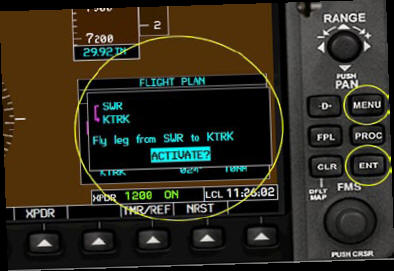 |
Press the MENU key to pop
up the Activate page,
then press ENT to activate |
5. Activate the SWR -> KTRK
leg by pressing the ENT key. Note that
if we activated the HNW -> SWR leg, we’d still
fly through the HNW VOR, so the effect of advancing to
this flight plan leg won’t take us directly to SWR.
Instead, we need to activate the SWR -> KTRK leg.
The effect of advancing the flight plan to skip the HNW
VOR and fly instead to the SWR VOR is that the G1000
turns the now-active leg red on the flight plan display
and should cause the aircraft to fly a great circle
route from the point of activation to the “direct to”
waypoint – the SWR VOR. With the current short flight
plan, the aircraft seems to continue flying the original
route through HWN, even though the display at the top of
the PFD shows KTRK as the next destination and the
flight plan display shows SWR -> KTRK as the
active leg. On the other hand, trying this on a flight
plan from Florida to California, and “going direct” to a
waypoint about 2/3 of the way along the route, the G1000
deviates from the original track (which is still
displayed on the MFD in white) and appears to fly a
great circle route to the “direct” waypoint.
Though the flight plan we’ve loaded uses VOR-to-VOR
navigation, the G1000 is not navigating by using VOR
radio signals. The VORs and related airways appear on
the G1000 display, along with other contents of the
G1000 navigation database. The original route was
“direct” from the SAC VOR to the HNW VOR, then along
V338 to the SWR VOR. The new route is along the V6
airway from the SAC VOR to the SWR VOR.
You can open Map View, press the V icon to display the
Victor airways, then move the mouse over the route legs
to pop up a box that displays the airway name and the
Minimum Enroute Altitude (MEA) for flying the route on
an IFR flight plan. We’ve chosen to fly along airways as
part of the tutorial, though aircraft with IFR certified
GPS often fly entire flight plans “direct.”
Pause the flight when over the SWR VOR. Altitude should
be 13,500.
GPS Approaches with the
G1000
Surprisingly, the FSX Learning Center description of the
G1000 does not contain the word “approach,” though use
of GPS approaches is increasing as GPS equipment use in
aircraft increases. There is information in the Learning
Center section “Using the GPS” that describes the
approach functions in the Garmin GPS 295 and 500
instruments, and the approach functions of the G1000 are
similar. GPS instruments such as the
G1000 can be used for other than GPS approaches, and the
G1000 database in FSX includes most worldwide instrument
approaches, whether GPS, ILS, VOR, NDB, LOC, etc. The
G1000 in real aircraft is “certified” for pilot
navigation and guidance for all types of approaches,
provided the database is maintained with periodic
updates, which must typically be downloaded and applied
every 28 days. Generally, only
horizontal guidance is available for flying approaches
with GPS instruments, though vertical guidance may be
available with certain GPS instruments equipped with
Wide Area Augmentation System (WAAS) capability, in
conjunction with designated Lateral Precision with
Vertical guidance (LPV) approaches. WAAS is a system of
satellites and ground stations that provide GPS signal
corrections, which improve position accuracy up to about
five times better than without WAAS, resulting in better
than three meters 95 percent of the time. Currently,
WAAS is available only in the United States.
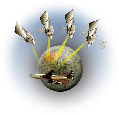 |
WAAS ground stations and
satellites provide
improved GPS accuracy in the U.S. |
Continuing the tutorial flight from
the paused position over the SWR VOR and Sierra Nevada
Mountains at 13,500 feet, assume we see clouds ahead. On
a real flight, we’d call ATC and request an IFR
clearance for an instrument approach to KTRK. Ignoring
the clearance and ATC communications for this tutorial,
we’ll discover the instrument approach features of the
G1000. Press Shift+3 and Shift+4 to
display popup versions of the PFD and MFD side by side.
On the right-hand sides of both, press the PROC keys.
You’ll see approach information pages pop up on both the
PFD and MFD, though the displays are different. With the
Select Approach line blinking in both displays, press
the ENT key on both. On the PFD page, you’ll see options
for both the GPS 19 and RNAV-A GPS approaches. On the
MFD page, the display will pop up a page with the GPS 19
approach only. If we select the GPS 19 approach on the
PFD by pressing ENT again, we’ll see a page pop up that
offers approach transition by Vectors, FMG (VOR), or
KEWFI (intersection). The MFD page initially offers
approach transition only by Vectors. The same approach
and transition options are available on the MFD as the
PFD, though a few more key and knob operations are
needed with the MFD and it’s slightly less intuitive, so
let’s close the approach pages on the MFD by pressing
the CLR key, and then focus on the PFD approach pages.
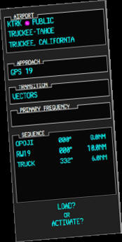 |
MFD approach page showing
Vectors transition
for KTRK GPS 19 approach |
To determine what the transition
options look like geographically, we need to consult the
effective instrument approach chart for the KTRK GPS 19
approach, as shown in the accompanying image.
The approach chart is oriented with north at the top,
and we’re approaching from the southwest. If vectored by
ATC, we might be cleared to AWEGA or OPOJI, but KEWFI is
labeled IAF for Initial Approach Fix. Let’s assume that
ATC clears us to the KEWFI intersection at altitude
13,000 feet, then based on the altitudes shown on the
approach horizontal and vertical profiles, we’ll likely
be cleared to descend to 10,800 at KEWFI.
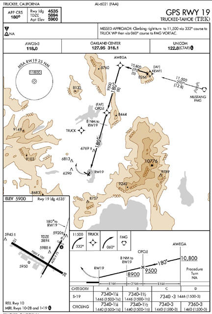 |
NOA Instrument Approach
Chart for KTRK GPS RWY 19
approach |
With the PFD approach transition page
open, click the + sign twice on the outer FMS knob to
move the cursor to KEWFI, then press ENT to select this
transition. Next, we’ll see the Load or Activate page,
with the cursor blinking on the Load command by default.
Click the + sign on the outer FMS knob to move the
cursor from Load to Activate, then press the ENT key to
activate the GPS 19 approach with KEWFI transition.
With the approach activated, the waypoint display at the
top of the PFD displays KEWFI and the autopilot will
provide heading guidance to KEWFI. The flight plan
display on both the PFD and MFD now shows the approach
waypoints: KEWFI, AWEGA, OPOJI, and RW19. The remaining
waypoints, 6300Ft, TRUCK, and FMG, are for the missed
approach procedure.

|
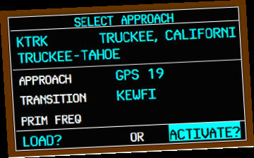 |
PFD approach
page showing three available
transitions for KTRK GPS 19 approach |
PFD “select
approach” with cursor moved to Activate |
 |
| MFD display of
approach and missed approach waypoints |
Continue the flight using the G1000
for horizontal guidance, while you change altitude in
accordance with the vertical profile of the approach
chart. The descent will be fairly steep, and it’s
important to slow to approach speed of about 100 knots.
Extend full flaps on final
approach. Continue descending to the Minimum Descent
Altitude (MDA) of 7340 feet. Then with the runway in
sight, continue the landing. Taxi to parking and then
reflect on what you’ve learned about operating the G1000
glass cockpit.
 |
| At Minimum Des cent
Altitude for GP S RWY 19 approach at KTRK |
*
Article
published under
Computer Pilot
license.
© Computer
Pilot
|

